|
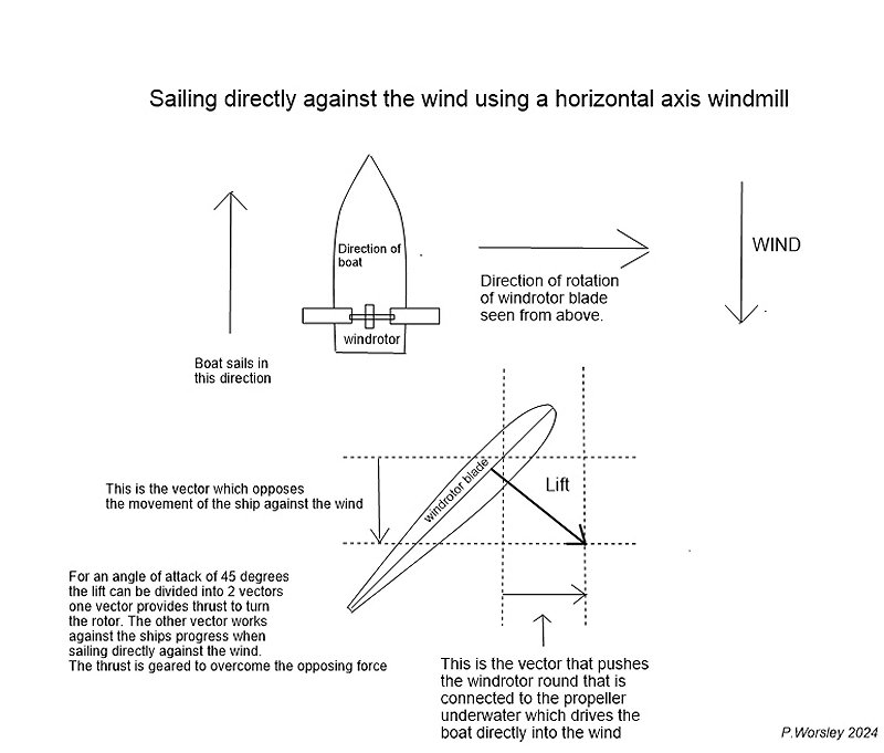
Explanation of diagram above
The diagram shows an example of the direct upwind craft which has blades set at an angle of 45 degrees.
Using this angle means the rotor will revolve slowly.
Because of this there must be enough blades
to cover the whole of the rotating disk not allowing any spaces for the air to pass through unused.
For example 6 blades or more of large area.
45 degrees in wind turbine terms means a tip speed ratio of 1.
Wind turbine "experts" will tell you that a tip speed ratio (TSR) of 7:1 is best
for obtaining the best power from the wind.
However, for maximum efficiency to take a vessel directly against the wind the lower TSR 1:1
I have found better from testing.
This should be made clearer from looking at the diagram.
Given that lift produced from these blades acts perpendicular to the blade surface.
The lift can be divided into 2 vectors, one which takes 50 percent to drive the boat and the other 50 percent will act in the wrong direction and tend to push the boat back.
So you have 2 opposing forces which counteract each other.
So how do we make the thrusting component overide the opposing component?
The answer is leverage. If the windblade is geared to the boat so that it moves a different distance than the boat, mechanical advantage comes into play. The boat itself acts as a fulcrum.
This has been very well shown on the landcraft tests of Rick Cavellero
Some have argued that the landcraft is much more efficient because it has a solid connection with the ground. However, watercraft that use very large slow rotating propellers have very good
grip on the water also.
So in the example above the windrotor needs to be geared that the blade rotates a distance greater than the boat and therefore the rotation force is greater than the opposing force.
For example if the blade distance rotationally travelled was double compared to the distance the boat travelled you would get double the force over the opposing force and therefore forward motion would be achieved. |